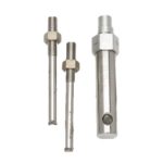
Inter-Connect Assembly
Product Description
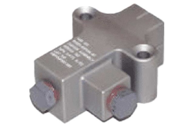
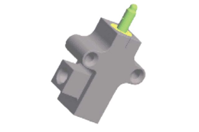
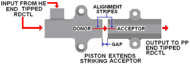
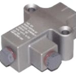
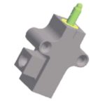
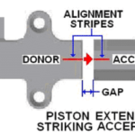
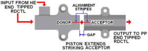
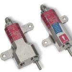
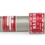
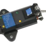
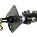
The Donor and Acceptor units make up the Inter-connect Assembly. The donor is a single or dual input port unit that has an extending piston. This allows for multiple inputs from alternate sources should a system require that feature. It functions when a detonating input is received from either a high energy end fitting from an ETL or a detonator (electrical or laser). The output energy of the ETL extends the Donor piston across the canopy sill line and through mechanical energy, strikes an Acceptor mounted to the canopy frame that is in-line with the Donor. The Acceptor Assembly is a receiving unit designed to function when struck by the piston of the donor. It can be either explosive loaded or inert. An explosive loaded Acceptor is designed with an internal transfer charge similar to those discussed in the previous Initiator section.
To function the Acceptor, the Donor’s piston strikes a piston on the Acceptor shearing a lip and driving a firing pin. In the explosive loaded acceptor the firing pin initiates dual percussion primers that initiate Lead Azide and then HNS resulting in a detonating output to an attached ETL. In the case of the inert Acceptor, the firing pin is driven in a percussion primer tipped RDCTL and initiates the ETL. The Acceptor allows the sequence to continue on to the canopy mounted CFS / TRS components. This Interconnect Assembly eliminates the need to disconnect components during canopy assembly removal. There is no flexible transfer line or connecting cable/linkage across the canopy sill required.
Key Features
How An Inter-Connect Assembly Works
Extensive Testing
PacSci EMC has performed extensive testing of the acceptor / donor configuration in the severest aircraft environments possible and in all cases the results have been successful.
Some environments include:
- temperature
- humidity
- salt/fog
- dust
- fluid exposure (fuel, hydraulic, cleaning solvents, etc.)
- sulfur dioxide
Additionally maximum gap and off set tests have been performed taking into account the non-static nature of canopy sills, acrylic transparencies and frame structures.
Specifications
- Operating Temperature
–65°F to +200°F - Leak Rate
1×10⁻⁵ cc/sec. Helium - Temperature, Shock, Humidity & Altitude (TSH&A) 28 Days
Per Mil Std-83124 at 80K Feet Altitude –65°F to +200°F and 95% Relative Humidity. - Shock
Per MIL-STD-810, Method 516, Procedure 1, 40 G for 11 milliseconds; 18 saw tooth shock pulses. - Vibration
MIL-STD-810 Method 514, Procedure I, Part 1, 2, & 3. Curve Z up to 2000 CPS with temperature range –65°F to +200°F. - Salt/Fog
MIL-STD-810, Method 509: 5%+1% Sodium Chloride by Weight for 50 Hours plus 48 Hours drying time. Fired at 70°F. - Dust
MIL-STD-810 Method 510, Except High Temperature 200°F. Dust concentration was .3 grains / ft., velocity was 1,750 feet/minute for a duration of 28 hours. All units fire successfully. - Iced Condition
MIL-C-83124 paragraph 4.5.11.10: Temperature –65°F & stabilized, then placed in 100°F/90% relative humidity until ice disappears, then –65°F & stabilized, then fired at –65°F - Submerged Operation
Submerged in 2 inches of water with gap completely filled with water. Fired successfully. - 6 Foot Drop
Dropped Firing Mechanism Up, Firing Mechanism Down and Side, then fired units successfully. - 40-Foot Drop
IAW MIL-STD-331A, Test 103.1 Procedure 1 Dropped Firing Mechanism Up, Firing Mechanism Down and Side. Units did not fire and were safe to dispose of. - Platform Use & Heritage
AV-8B, JAS-39, T-38A/N, T-6, Concept Aircraft, Improved CFS w/Inert
