


Start Cartridge
Product Description
What is a Start Cartridge? Our cartridges are specialized gas generators that produce gas pressure from propellant grains to start turbojet engines. The output can be customized to specific performance factors for engine design. The cartridge is initiated with a 1-amp/1 watt electro-explosive device (EED) which can be initiated with standard battery power. With the addition of a PacSci EMC Igniter, you have all the components for a tailored engine start system for your program.
Key Features
The Design Process
A start cartridge, or ‘start cart’, takes a firing impetus and spins up a turbine. Inside the cartridge we’re taking a low-level input from either a pyro line or an electric initiator to provide a significant amount of heat and pressure to then light off the propellant grain.

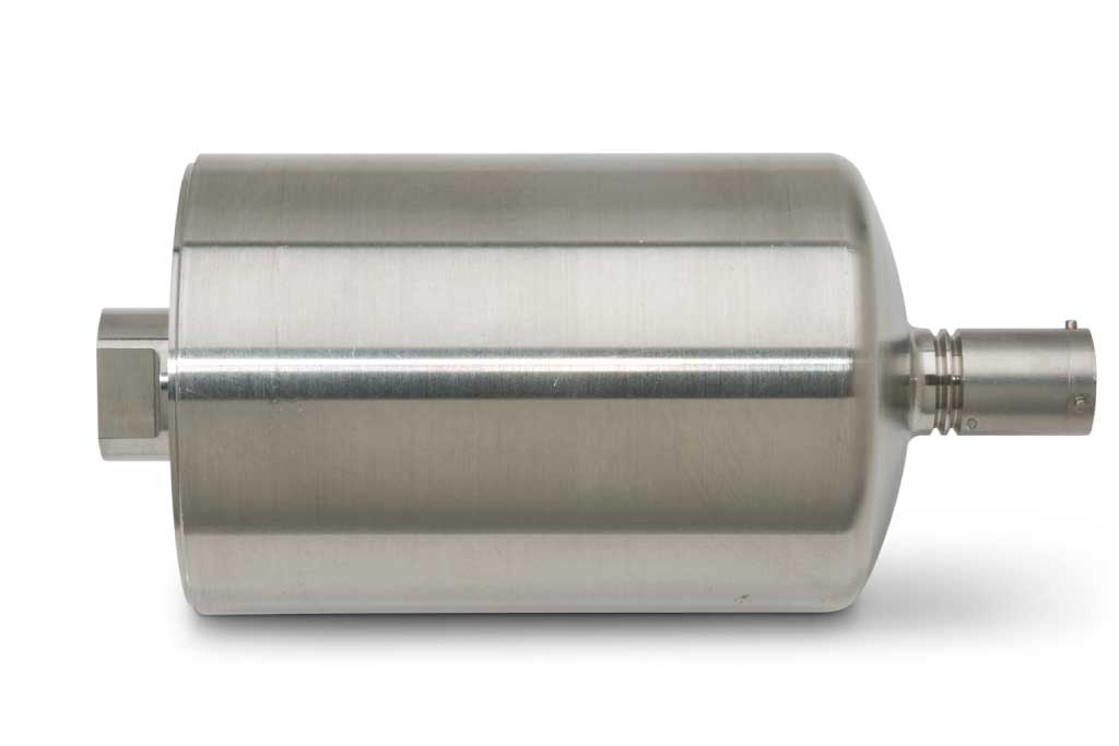
The propellant grain is a solid fuel, and it evolves off gas as it burns. That gas is what gets accelerated or pushed out the nozzle (shown left) to hit the turbine, getting it spinning. When the turbine is spinning, it will charge up the combustion chamber preparing it for ignition.
The first step in the process is to figure out what size cartridge you need in terms of energy. This requires assessing how much energy it is going to take to get the turbine up and spinning to the point it’s going to be stable for combustion in all situations.
To that end, customers look at the environmental extremes in terms of what temperature conditions the turbine is going to be working in. Also, the airflow over the inlet is evaluated, and whether there are covers that have to come off, the timing of those covers, etc. They also look at the angle of attack: if it’s dropping off a wing or coming out of the bay. Essentially, looking at the longest time those elements are going to take to spin up and charge the combustion chamber as it’s getting power. There are a lot of mechanical factors customers must consider that are part of their system. Things like the turbine efficiency from the blades, how fast the compressor can start pulling in air, and turbine inertia. The turbine is going to resist that rotational motion at the beginning, not just from lubrication and drag, but also from inertia. The gas from start cartridge provides the energy required to get the mechanical components up to speed.
With those inputs defined, we look at where we can impinge on the impeller, and from there figure out how much time and horsepower it’s going to take. Once the calculations are done,

there are two ways of flowing the requirement down to us. The first is pressure and temperature at the output over that period of time, and that’s what you see in the graph on the left. The graph is displaying a time pressure curve of the output of one of our units.
All this analysis is performed and refined to just inside the nozzle prior to the restriction. It’s a pressure over a given period of time. There’s a temperature requirement that goes along with this as well. It’s essentially adiabatic flame temperature of the composition, a little bit lower, but it’s right there at the nozzle. This becomes the Pressure/Time/Temperature curve.
The other way of defining the requirement is the gas horsepower equation. Essentially the mass flow rate multiplied by the adiabatic head, again by calculating the pressure right at the beginning of the nozzle before the choke point. This defines how much power is coming out of the start cartridge.
Ultimately, we take one of those two numbers as our specification, gas horsepower with time or, pressure with time. From there, we can get an idea of how much energy needs to be in the start cartridge.
Initiation – Two Methods
The next design input is initiation: figuring out what the input signal, that first impetus, will be to get things going.


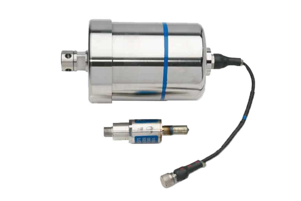
We’ve come a long way from the initial pyro line model with the advent of robust electric ignition systems (radially outward firing unit is an example shown at right). We have ways of testing EMI now and understand shielding requirements and testing techniques to validate EMI protection that we didn’t before. Because of this, the electric ignition system is now favored over a pyro transfer line system. The electric ignition system has more flexibility and is easier to handle and manage the electric lines. This method tends to be the more modern configuration, but both are still used and are acceptable. PacSci EMC can design with both.
Propellant Selections
With initiation defined, the next design element is propellant. There are two primary choices: Ammonium Perchlorate based and Ammonium Nitrate based. Both types can provide the
Generally, in a rocket propellant, you want a super-hot exhaust with a massive velocity, optimizing the system around stoichiometric chemistry. In a start cartridge, you want to run rich because you want a cooler combustion product than you’d normally see in a rocket engine. You’re still inside a turbine engine and impinging. The gas is directed at the compressor as opposed to directly into the hot section and those compressor components aren’t generally designed to withstand very high temperatures. We cool the combustion by running it rich. Some of the carbon and by-products can recombine further downstream when air is introduced into the system through the inlet. This can lead to a little extra
kick. This is not the primary intent of a rich mixture though; the goal is to cool the exhaust.
There are two major differences between the ammonium perchlorate based system and the ammonium nitrate based system. The ammonium perchlorate base is naturally phase stabilized, meaning that through temperature changes, it doesn’t change its phase. The crystalline structure of the ammonia perchlorate doesn’t expand and contract on its own so it’s very stable. It’s also very moisture resistant. These characteristics make it resemble nice, solid plastic chunks that are easy to work with and easy to store.
Ammonium nitrate is much less forgiving, however there are reasons it has a long history and continues to be used today. There’s a solid understanding of what its limitations are and how to manage and control them. Primarily, the issue is moisture. Typical ammonium nitrate will expand and contract as it passes through normal storage temperatures like temperature cycling in a bunker or in a ship. This is not a typical coefficient of thermal expansion; it is a change of the crystalline structure driving the propellant to break down mechanically. This turns it back into somewhat of a powder, which gives you a lot more surface area. When you light off a powdery grain it burns much more quickly than anticipated. This can result in a fast burn and catastrophic failure of the cartridge.
In ammonium nitrate-based propellant, the crystalline structure can be stabilized. As it passes through normal storage temperature, when it’s in
that phase stabilized state, it does not change its crystal structure and it remains mechanically stable. However, when it’s exposed to moisture, it loses that phase stabilization, and is then subject to potential failure.
Engine Integration
Once the start cartridge is designed, in terms of how much energy is needed and amount of propellant, we work with our customers to package the start cartridge into a shape that fits within their system. We meet their mechanical requirements as well as the specification for starting the engine and getting it spinning.
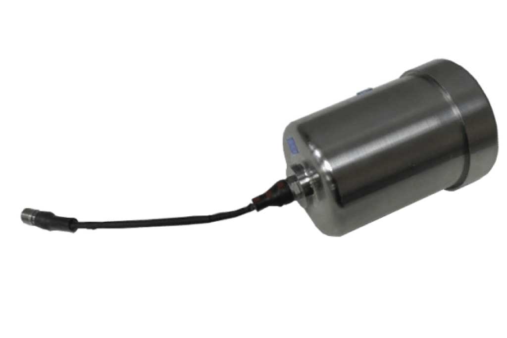
The picture (Figure 6) shows a turbine engine used in the MALD system. In the upper right-hand corner is a PacSci EMC start cartridge mounted on the engine. It’s a fairly large package. All the propellant is in a single unit, and you can see trailing off to the to the left is the electric ignition system. The pig tail is attached to a connector that ties it into the rest of the system.
From a slightly different angle (Figure 7) you can see more of the nozzle end. The exhaust from the start cartridge comes out facing the inlet to the engine. A manifold directs it off into two directions. Those two points impinge on the edge of the compressor, which then flow out through the hot section in the engine.

against the compressor blade. From there it will flow into the combustion chamber and then out the hot section. While there are many details, that completes the basic high level design
steps used to create a start cartridge. That’s the ‘turn’.
If you are interested in the “burn” of Rocket Motor Ignition head on over to here.
Specifications
- Bridgewire
1 ± .1 ohms - Function Time
<10 mSec - Burn Time
2 seconds minimum - Cartridge Burn Time
2 minutes minimum - All-Fire
3.5 amps, 10 ms. pulse - No-Fire
1 amp/1 watt for 5 minutes - Function
This device produces an exhaust gas with a temperature of less than 2200 oF.
Produces approximately 1500 psi for a minimum of two seconds when fired with a .144″ diameter equivalent orifice. - Operating Temperature Range
-65 0F (-54 0C) to +160 0F (+71.11 0C)
FAQ's
-
What is a Start Cartridge used for?
We have tailored cartridges to specific missile and drone applications. This product is optimized for small turbine engines used in missiles, air launched decoys, targets and drones.
-
What is a Start Cartridge?
A start cartridge is a specialized gas generator that produces gas pressure from propellant grains to start turbojet engines.

