


Time Delay Initiators
Product Description
Time Delay Initiators (TDIs) are used to properly sequence time (from milliseconds to hours) and events in a system. They are used in emergency egress, missile, space and oil and gas systems. Each application may have multiple delay times, inputs, outputs and configuration options.
Key Features
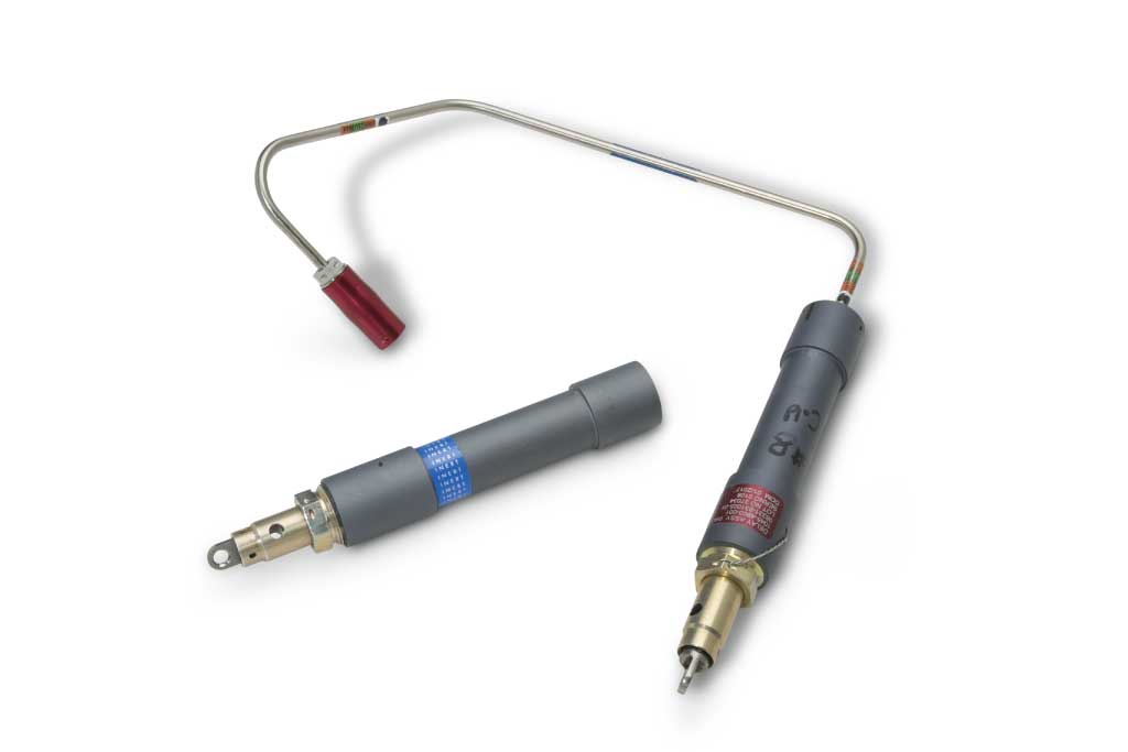
The description provided in this section will focus on aircraft Emergency Egress Systems (EES). TDI’s can accept both hot gas and detonation inputs to initiate and provide likewise as an output. Our TDIs have been incorporated on ejection seats and within Canopy Removal System / Transparency Removal System and canopy jettison systems.
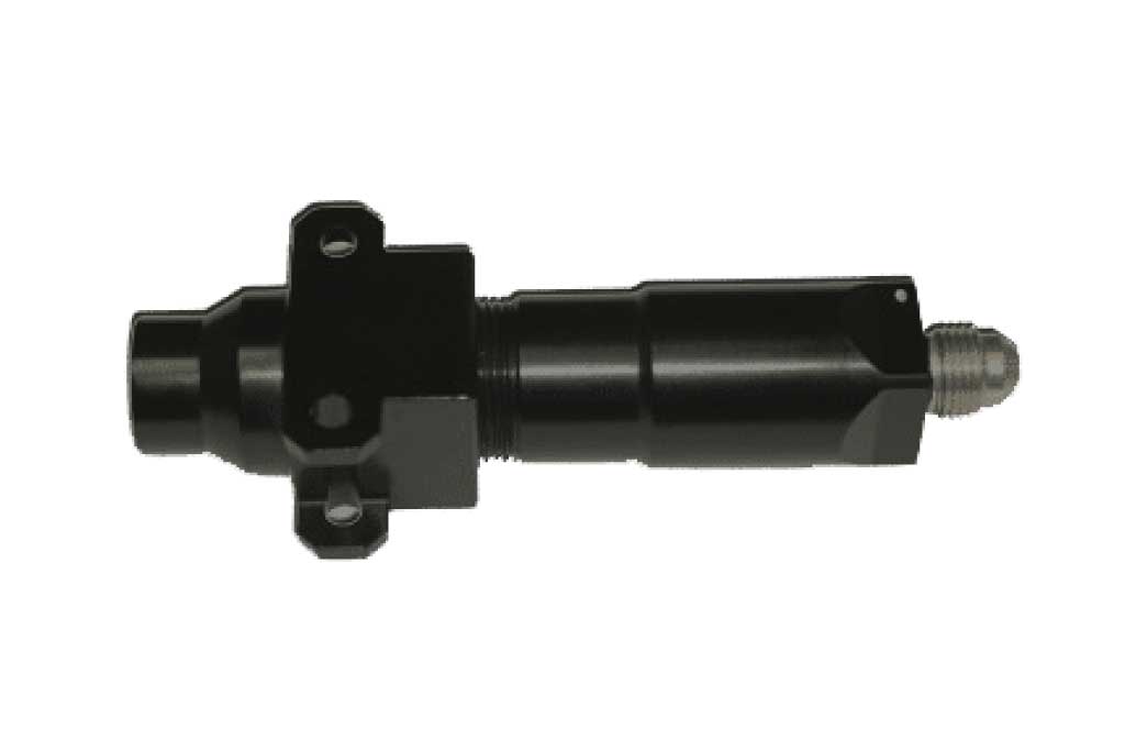
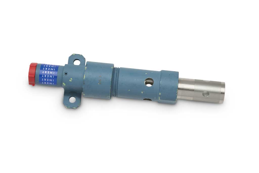
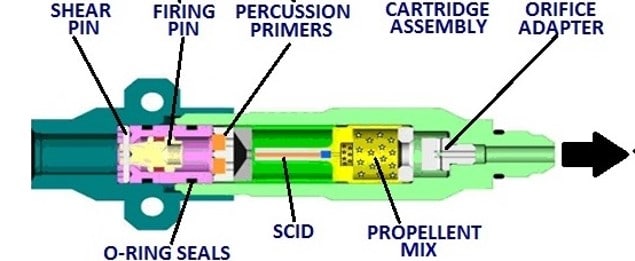
TDIs are initiated by hot gas pressure, output from an Explosive Transfer Line (ETL) HE End Fitting or mechanical. Upon receipt of a gas, detonating or mechanical pull signal an annular firing pin releases and is driven into dual percussion primers. The primers fire and ignite the delay element called Small Column Insulated Delay (SCID). After the SCID has burned for its allotted time it ignites a gas generating charge or high energy transfer charge output. The gas output flows from the bottom of the initiator through a filter into the ejection seat and attaching sequencing system. A detonating output fires and an attached SCID is used to provide a time delay tolerance of approximately ±15% maximum across the operating temperature range of -65°F to +200°F for EES’s. To ensure the proper TDI is installed into the proper position a combination of different anodized / painted body colors and various thread sizes are used to identify individual units. Mounting provisions to secure the TDI are machined into the initiator mounting flange.
A NEW ELECTRONIC TDI
PacSci EMC is developing a new Electronic TDI (eTDI). It is using PacSci EMC P/N 826852 (US Navy WB55), 0.3 second Time Delay. This time delay is currently installed on the NACES Ejection Seat in the F-18 and T-45 aircraft. Power source is a Lithium Battery with energy release by firing pin impact. Energy flows to a PWA capacitor. The capacitor stores the energy until required to fire the output charge that is initiated by a Reactive Semi-Conductor Bridge. Advantages of the delay include, improved accuracy (+ 5% across temperature range of -65°F to +200°F) and increased service and shelf life. This effort will be for gas actuated TDI’s. The delay cartridge consist of the initiation element, power source and electronic package, similar in size to a .45 caliber bullet. Current schedule is to complete DVT by March 2018. A total of 43 full up units will be manufactured and tested in preparation to enter into a Critical Design Review (CDR) and qualification testing.
Specifications
- Operating Temperature
–65°F to +265°F - Leak Rate
1×10⁻⁵ cc/sec. Air at 1.0 + 1Atmosphere - Temperature Cycling
100 Cycles of –65°F for 55 minutes to +203°F for 45 minutes. No adverse effect to initiators. - Altitude
Per MIL-STD-810 Method 500 Procedure II. 100 cycles of 0 to 70,000 feet with ports open. No adverse effect to initiators. - Shock
40 G with nominal duration of 11 milliseconds on all axes for a total of 18 impacts per axis. - Vibration
Sinusoidal and Random Vibration Cycles at 5-100 and 20 to 2000Hz and amplitude levels of .20 inches double amplitude and + 10g, over temperature range of –65°F to +200°F - 6 Foot Drop
Per MIL-STD-810, Dropped Firing Mechanism Up, Firing Mechanism Down and Side, then fired successfully. - Function Time
Delay time will be within + 25% of delay time over the temperature range of –65°F to +200°F. - Auto-ignition
Exposed to 350°F for 1 hour without firing. - Salt/Fog
MIL-STD-810, Method 509: 5%+1% Sodium Chloride by Weight for 48 Hours plus 48 Hours drying time. Fired at 70°F. - Humidity
Per MIL-STD-810 Method 507 Procedure I except relative humidity was 100% and temperature +200°F for 240 hours with no adverse effect. - Platform Use & Heritage
B-1B, F-111, F-15, F-18, T-6, T-38, F-5, Alpha Jet, Horizon, Premier I
Interface

