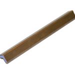
Linear Shaped Charge
Product Description
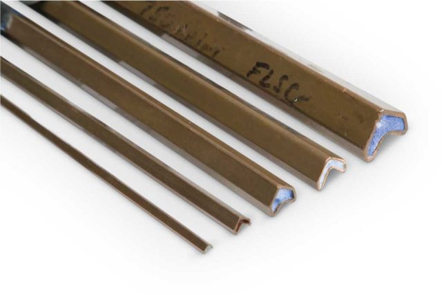
Linear Shaped Charge (LSC) is used to cut various types of metal in separation systems, from launch vehicles to missiles, in space, military and underwater applications. Linear Shaped Charge is a continuous explosive core enclosed in a seamless metal sheath, formed into an appropriate shape to sever the target.
Normally the shapes are either a chevron or inverted “V” shape or similar to the profile of a ‘house’. The type of metal determines the flexibility of the charge. Chevrons for Flexible Linear Shaped Charge (FLSC) are easier to form intricate patterns for a Canopy Fracturing System (CFS). The house shape is for more ridged designs especially for Flight Termination or Separation Systems by LSC assemblies. These shapes provide what is known as the “Munroe” effect when the linear shaped charge is detonated. The Munroe Effect is the reinforcement of shock waves in a hollow charge, concentrating the effect of the explosion along the axis of the charge. In this case, the Munroe Effect is enhanced by carefully controlling the charge dimensions and configuration for each application.
The metal sheath liner is most commonly formed using copper, aluminum, lead or silver. Generally, most large core loads utilize copper however for structural integrity Aluminum is recommended. When it comes to flexibility and with small core loads a lead liner is recommended. Silver is primarily used with thermally resistant explosive core loads. As for the powders most commonly used, there is RDX, HMX, PETN and HNS.
Upon detonation, the continuous metal sheath liner and explosive produce a uniform linear cutting action. PacSci EMC will determine the best combination of explosive core and metal sheath to sever the target specified. Factors such as the type of target material, its thickness, operational temperature exposure, standoff distance, vibration, shock, etc. assist in determining the proper LSC / FLSC.
Key Features
- Qualified to RCC-319, Space/Aircraft ref
- Choice of core load, explosive & sheath
- Easy integration into aircraft, missiles & space vehicles
- Reliable initiation with PSEMC detonators & ETLs (FCDC, CDC, SMDC & RDCTL)
- Flexible integration with other PSEMC system components from initiation to cutting event
- Collateral damage & debris risks minimized with retainer / charge holder designs
How Linear Shaped Charge Works
Output from an electric detonator, an exploding foil initiator or high energy explosive transfer line initiates the LSC or FLSC. The LSC or FLSC explosive material generates a detonation high pressure wave traveling through its length. The focusing of the high-pressure wave collapses the metal sheath forming a high velocity metallic jet. The jet pierces the target wall (metal, composite, acrylic, etc.). The detonation projects into the lining, to form a continuous, knife-like (planar) jet. The jet cuts any material in its path, to a depth depending on the size and materials used in the charge. The Hydrocode simulation below shows one of our designed charges before, during, and after the functional event, illustrating the LSC / FLSC Monroe Effect.
LSC / FLSC is available in a variety of sheath and explosive materials. Core-loads (explosive per unit length) range from 8 grains per foot to 800 plus grains per foot. Detonation velocities, depending on the sheath and explosive type, ranges from 6,000 to over 8,000 meters/second. . PacSci EMC LSC / FLSC severs aluminum, steel, copper, composites (solid and honeycomb), specialty alloys, titanium, polycarbonate, acrylic (stretched and cast) and laminate materials. Thickness vary from hundredths of an inch to over 2 inches, depending upon the application.
Many applications require a mounting assembly to secure the LSC / FLSC to a platform. PacSci EMC designs these assemblies to provide the optimum standoff for the LSC / FLSC as well as an initiation port for securing a electric detonator, Exploding Foil Initiator (EFI) or Explosive Transfer Line (ETL) such as a Flexible Confined Detonating Cord (FCDC) with a high energy detonating output. The LSC / FLSC will also be formed to meet the contours of the inner or outer mold lines of structure (metallic, composite, acrylic/polycarbonate, etc.) as necessary to ensure a uniform severance of the target, as required. Back-blast attenuation material is available to incorporate with the LSC or FLSC to prevent damage to surrounding equipment or injury to aircrew members. The attenuation material ranges from a metal retainer to low density plastic foam or silicone rubber, depending on specific requirements.
We conduct a series of sizing tests to ensure the proper LSC or FLSC is part of the design from the beginning. We use our expansive experience to narrow down the candidates validating the final choice with firings after temperature conditioning. We will accept customer furnished materials or purchase representative materials to conduct the tests at maximum expected thickness. Once complete, the design of the assembly and integration into the platform will start in earnest.
A great overview, although rather dated, of LSC shock effects and literature was done by NASA and can be found here.
Specifications
- Typical Environments (from across several Aerospace & defense applications, Mil-Standards and program focused requirements)
- Leak Rate: 1×10⁻⁵ cc/sec, air at 1 atmosphere (2.7 x 10⁻⁵ cc/sec. HE)
- Thermal Performance: -65°F to +210°F
- Temperature, Shock, Humidity & Altitude (TSH&A): Temperature range of -65˚F to 160˚F, 95% relative humidity, altitude of 70,000ft and exposed for 28-days.
- Vibration: Frequency ranged from 15 to 2000 Hz,, A = 0.015 g^2/Hz, W0 = 0.015 g^2/Hz, B = 0.003 g^2/Hz, Grms = 4.6, Duration 9.6 hours per axis
- Shock: Service Shock, 18 shocks applied (6 in each axis) with frequencies ranging from 10 to 1000 Hz and SRS G levels to 62G’s, Crash Shock, 40G, 11ms, terminal peak saw tooth applied in opposite directions, each axis
- Acceleration Load Test: Ultimate Acceleration: X-axis: ±15G, Y-axis: ±15G Z-axis: +16.5/-15G, Ultimate Angular Moments: Roll rate: ±6.75 rad/s, Pitch rate: +2.64/-7.8 rad/s. Yaw rate: ±5.25 rad/s, Roll acceleration: ±27 rad/s2, Pitch acceleration: ±15.0 rad/s2, Yaw acceleration: ±3.0 rad/s2
- Salt Atmosphere (including S02): Exposed units to a 5% salt solution of 95˚F±5˚F for a period of 168 hours. The pH of the solution was in the range from 2.5 to 3.2. A constant salt spray with SO2 gas introduced for 1 hour, 4 times a day (every 6 hours) per ASTM G85.
- Sand & Dust: Particle size between 1 and 1000 microns with most between 150 and 500 and a concentration of 2.19 grams/m3 and air velocity at 18 m/s. Temperatures up to 145°F. Total test time is 28 hours.
- Humidity: Temperature range: -65˚F to 160˚F, 95% relative humidity, altitude of 70,000 ft. and exposed for 28-days
- Rain: Durations & rates: 1 hour – 4.72 in/hr. rainfall at 108 ft./sec, 12 hours – 1.10 in/hr. rainfall at 84.5 ft./sec, 24 hours – .71 in/hr. rainfall at 67.6 ft./sec
- Air Pressure: 65 psia to 14.7 psia, Pressures applied and removed at rates greater than those specified
Specification Questions
If you are interested in Linear Shaped Charge for an application you are working on, we will ask for some basic information to assist with your program. Below are some questions we may ask to better understand you requirements.
- What is the target material type? Is it manufactured to a specific document (military specification, company material document, STANAG, etc.)
- What is the maximum thickness of the target material?
- What type of initiation do you require (Electric Detonator, ETL, EFI, etc.)
- What type of system will the LSC / FLSC be used (FTS, Stage Separation, CFS, Hatch Severance, etc.)
- Is there a specification or Statement of Work (SOW) available detailing the environments and available envelope for the LSC / FLSC?
- Do you require the LSC in cut lengths? If so, how long?
- How much LSC do you require?
- Is this for a one-time opportunity or is there a production future?
FAQ's
-
What is a linear shaped charge?
A Linear Shaped Charge acts as a cutting mechanism for separation systems in aircraft, launch vehicles and missiles. Our LSC / FLSC consists of a continuous explosive core enclosed in a seamless metal sheath, formed into an appropriate shape to sever the target. Normally the shapes are either a chevron or inverted “V” shape or similar to the profile of a ‘house’.
-
How do shaped charges work?
In Linear Shaped Charges, the LSC or FLSC explosive material generates a detonation high pressure wave traveling through its length. The focusing of the high-pressure wave collapses the metal sheath forming a high velocity metallic jet. The jet pierces the target wall (metal, composite, acrylic, etc.). The detonation projects into the lining, to form a continuous, knife-like (planar) jet. The jet cuts any material in its path, to a depth depending on the size and materials used in the charge.
-
What is the Munroe effect?
These "V" or chevron shapes provide what is known as the "Munroe" effect. When the linear shaped charge is detonated the shockwaves follow the form of the shape creating a uniform cutting action.
-
How does the Munroe effect work?
The Munroe Effect is the reinforcement of shock waves in a hollow charge, concentrating the effect of the explosion along the axis of the charge. In this case, the Munroe Effect is enhanced by carefully controlling the charge dimensions and configuration for each application.
