PAUL SCHWEIGER | DIRECTOR OF BUSINESS DEVELOPMENT, SPACE AT PACSCI EMC
SPACE HERITAGE & RECENT ACCOMPLISHMENTS
PacSci EMC has been supporting both launch vehicles and on-orbit assets for over 70 years. We have a great deal of experience in this area, recently leveraging our core capabilities in both electronics and pyrotechnics. Our experience and capabilities allow us to provide low risk solutions for a wide variety of applications with literally thousands of products in our catalog
PacSci EMC has 70+ years of heritage in space qualified, electronic and pyrotechnic system design, manufacturing, packaging, test and integration.
Our heritage, unique system design, and commercial of-the-shelf (COTS) hardware at TRL-9 provide low risk solutions for many launch vehicle and space applications.
Satellite sequencing hardware has been flight tested in space
► 428 Satellites deployed (as ofFeb 20220)
► 3,424 Events sequenced
► 100% Success
PACSCISAT tested hardware in orbital environments
► Smart Initiators, Controller andConnectors
► MAPS(TM) Solid Propulsion
► Space Standard Initiator
A view of our most iconic space related components
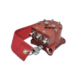
MECHANICAL SAFE & ARM
The workhorse of our heritage FTS systems for decades
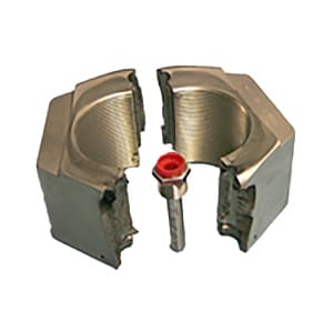
FRANGIBLE NUT
This particular frangible nut was used as part of the space shuttle hold down and release system, which had a load carrying capability of over 1.1 million pounds.
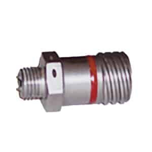
ATLAS STANDARD INITIATOR
This is one of over 500 unique initiators and detonators used on countless platforms in its application on the Atlas launch vehicle. As many as 65 of these were used per flight to start a variety of different pyrotechnic events
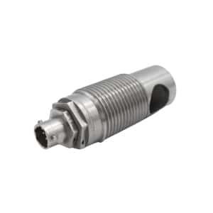
MECHANICAL SAFE & ARM
The pyrotechnic cutter shown was used on Osiris REx to release the asteroid sample container into its storage bay for the return flight to earth
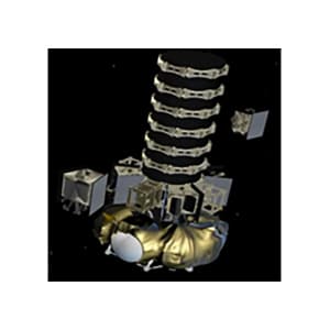
SMART ENERGETIC ARCHITECTURE (SEA(TM))
Dispenser system for deploying satellites. For this application we provide our SEA (TM) system to command the release of these satellites in orbit with over 428 satellites deployed today with a 100% success rate.
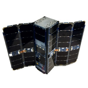
PACSCISAT
A 3U cube sat flown as a technology demonstrator to show on orbit capability for our smart, energetic architecture, as well as our small sat propulsion system and our space standard initiator, a NASA standard initiator equivalent.
All the critical functionality we support:
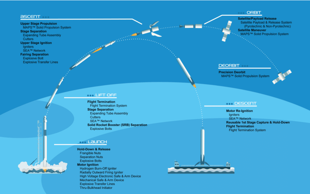
PacSci EMC is present in all phases of the launch, boost separation and on-orbit activity. From hold down release systems (such as the space shuttle frangible nut) all the way through to our sequencing and deployment capability, satellite propulsion systems and finally, motor ignition systems for booster recovery operations.
SPACE INFORMATION LABS (SIL)
Space Information Labs (SIL) is a small business based in Santa Maria, California near Vandenberg Space Force base. They are a full design, manufacturing and environmental test capability building flight units, from REITs Thomas flight termination to space-based range and lithium ion battery units. They are a fully qualified AS9100D quality management system to design and build flight hardware.
► Primary business is Space R&D and missile flight unit products for Prime Contractors and Federal Agencies including AFSPC, SMC, MDA, AFRL, NAVAIR, DARPA and NASA
► AS9100D QMS to design, manufacture and environmental test of Avionics, AFTS, GPS Tracking, and Li-Ion Battery Flight Units
► DCMA Master Inspection Points (MIPS) at SIL for Missile Flight Units delivery
THE PACSCI EMC/SIL PARTNERSHIP
With PacSci EMC’s heritage Flight Termination Systems (FTS) and SIL’s unique capability with vehicle tracking and FTS batteries, together we provide a complete plug and play Autonomous Flight Safety System (AFSS). The plug and play components break down as such: Safe & Arm Devices (SADs) and explosive subsystems from PacSci EMC and from SIL the Vehicle Based Independent Tracking System (VBITS) Autonomous Flight Termination Unit (AFTU) and Li-Ion batteries.
PACSCI EMC SUBSYSTEM
► Safe and Arm Device
► Explosive Transfer Lines
► Exploding Foil Initiators (Detonators)
► Destruct Charge
SIL SUBSYSTEM
► Vehicle Based Independent
Tracking System (VBITS)
► Autonomous Flight Termination
Unit
► Li-Ion Batteries
A SIDE NOTE ON TERMINOLOGY
As a disclaimer here, we may use a few terms
interchangeably:
► flight safety system
► flight termination system
► thrust termination system
There are some nuances to the specific meanings
of these we may touch on in future articles.
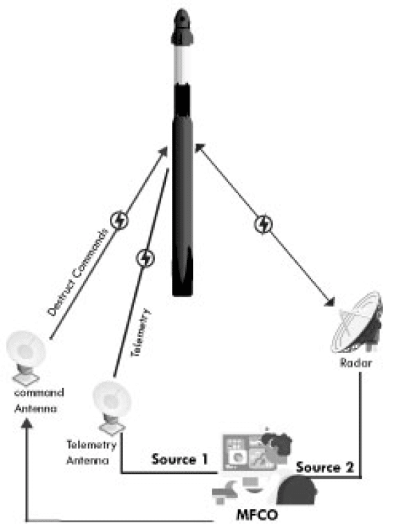
Traditional FTS
FLIGHT SYSTEMS:
Flight Terminiation System
- Safe & Arm
- Receiver
- FTS Logic Box
- Battery
- UHF Antenna
- Hybrid Coupler
- Ordnance
Metric Tracking
Sources (RCC 324)
- GPS
- L-band Antenna
- Couplers
- Power Distribution Box
- Vehicle Battery
- Telemetry Encoder
- Telemetry Transmitter
- S-band Antenna
Radar Transponder
- C-band Antenna
- Hybrid Coupler
- Power Distribution Box
- Vehicle Battery
GROUND SYSTEMS
Command Systems
- Power Supplies (Redundant Sources)
- Antennas (Omnis & Directional)
- Amplifiers (10kW Tubes)
Telemetry Receivers
- Antennas
- Decoders
- Ground Communications Network
Radars
- Radar Sites
- Ground Communications Network
- Timing Infrastructure
Mission Flight Control
- MFCO
- Telemetry Officer
- Certified Displays
OPERATIONAL
CONSIDERATIONS
- Telemetry Formats
- Telemetry Constraints
- Launch Constraints
- Range assets are degrading and/or being decommissioned
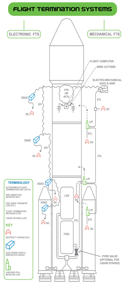
Launch vehicles capable of leaving a range and thereby endangering a protected area are required to have the capability to terminate the flight. This system is used if the vehicle deviates from its intended flight path, violating a limit line which has been established as part of a hazard analysis.
The traditional way of doing this relies heavily on both onboard
components and significant ground support infra-structure. On the vehicle, a radar, a transponder and its associated antennas and couplers are tracked by ground radar sites. That information is relayed through ground communication networks, back to a flight control console where a safety officer is analyzing the
real time data to flight trajectory plan and comparing the telemetry.
If there’s a violation of a limit line, the officer would issue a terminate command back to the vehicle using ground-based communication networks and transmitters. On the vehicle this would be received by a flight termination receiver which has its associated antennas and couplers.
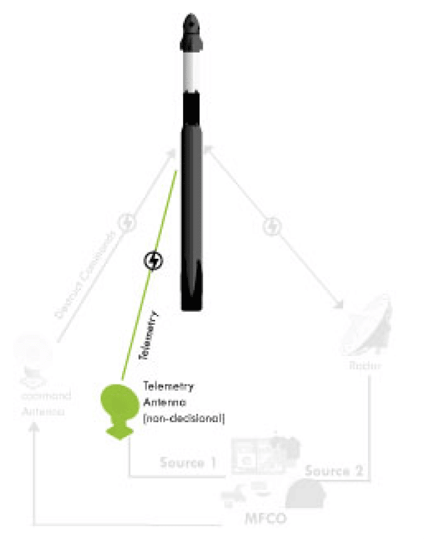
Autonomous FTS
FLIGHT SYSTEMS:
Flight Terminiation System
- autonomous Flight
- Termination Unit
- Thrust Termination/
- Ordnance
- Safe & Arm
- Receiver
- FTS Logic Box
- Battery
- UHF Antenna
- Hybrid Coupler
OrdnanceSafe & Arm
Metric Tracking
Sources (RCC 324)
- IMU/INS
- GPS
- L-Band Antenna
- Couplers
- Power Distribution Box
- Vehicle Battery
- Telemetry Encoder
- Telemetry Transmitter
- S-band Antenna
Other
- Mission Data Load
Radar Transponder
- C-band Antenna
- Hybrid Coupler
- Power Distribution Box
- Vehicle Battery
GROUND SYSTEMS
Command Systems
- Power Supplies (Redundant Sources)
- Antennas (Omnis & Directional)
- Amplifiers (10kW Tubes)
Telemetry Receivers
- Antennas
- Decoders
- Ground Communications
- Network
Radars
- Radar Sites
- Ground Communications Network
- Timing Infrastructure
Mission Flight Control
- MFCO
- Telemetry Officer
- Certified Displays
OPERATIONAL
CONSIDERATIONS
- Telemetry Formats
- Telemetry Constraints
- Launch Constraints
- Range assets are degrading and/or being decommissioned
On an autonomous flight safety system, we’ve moved the tracking and decision making capability to the vehicle thereby eliminating the vast majority of the ground support infrastructure required or, at the very least, reducing those assets to non-safety critical.
The tracking and decision-making capability have been moved to the vehicle. This is done by the introduction of a new device, an Autonomous Flight Termination Unit (AFTU). This device tracks the flight of the vehicle either using internal or optional external sensors, or a combination of the two. It’s comparing the flight to a set of preloaded mission flight rules known as the mission data load. If one of those rules is violated, the AFTU will issue the terminate command.
How?
► Tracking and flight termination decision moved to Autonomous Flight Termination Unit (AFTU) on the vehicle
► Tracking data from internal / external GPS and INS sensors
► Mission Data Load (MDL) – rule set built in pre-flight
► If a rule is violated the flight is terminated
Why use an AFTU?
KEY BENEFITS INCLUDE:
Reduction in the vehicle assets:
► Radar stations
► Command transmitters
► Communication network
► Telemetry down-link no longer safety critical
Ground support personnel:
► Reduction in the ground assets that are required for launch
► Flexibility in launch locations (new launch sites with a potential for
increased launch cadence)
► Reduction in costs associated with each launch attempt
Eliminating the human factors:
► Reaction times
► Potential for errors in human decision making
And then finally there is a mandate, at least in the United States, to be fully
autonomous by 2025.
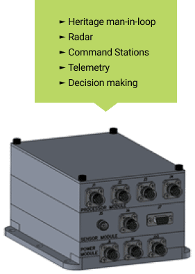
Autonomous Flight Termination Unit (AFTU)
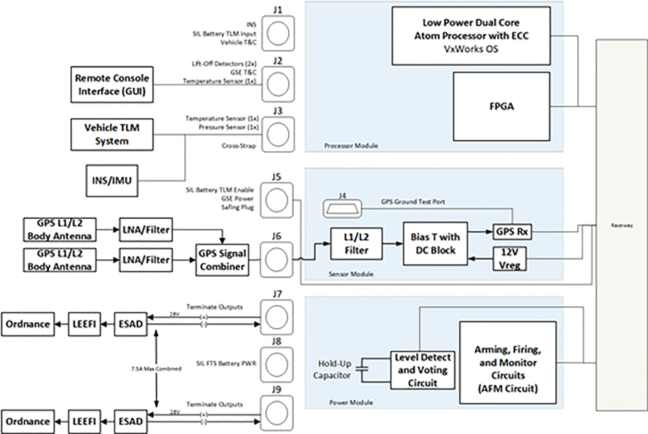
The three stackable modules are Faraday cages. The bottom module is the power and destruct logic module. If you will notice, on J7 and J9, there are two termination outputs. Per Range Safety requirement we incorporate two independent termination outputs feeding to the PacSci EMC ESADs, LEEFIs and ordnance strength.
The center module which contains the sensor has the GPS receivers, holding up to two receivers. There is a built in L1/L2 filter inside the unit. If something on the launch vehicle got close in frequency, the GPS has a band pass filter in front of everything.
The T bias can power the external LNAs right up the RF cables, plug and playing into the LNA amplifiers on the launch vehicle. With two antennas, and an LNA behind it, coming into a combiner and the GPS receiver
sensor module.
The upper module is the brain, the processor in com. FPGA that handles all the comports is about seven or eight com ports.
The unit is running VX works, and with custom written On-Watch. The On-Watch Wrapper software is running CASS OR3, the latest version of the air force software available.
Currently, SIL is at tier level 7 with this technology. Flight testing is on deck. In 2023, at Vandenburg Space Force Base, a range tailoring program is scheduled with Range Safety. Once this has been accomplished our AFTU will be blockable to Cape Canaveral or Vanderburg.
To make use of the signal provided by the AFTU we must build out the rest of the FTS system, beginning with a Safe and Arm Device (SAD). There are three approved SAD technologies to choose from
Laser Firing Units
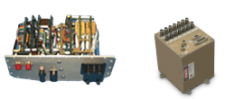
Laser Firing Units provide fiber optic guided infrared radiation pulses to safely and reliably initiate many types of explosive and pyrotechnic output devices—deflagration, detonation, ignition, pressure and gas generators.
Mechanical Safe and Arm Units
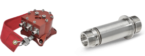
Electro-mechanical Safe & Arm Devices incorporate internal rotors or barriers to separate primary and secondary explosives.
High Voltage Electronic Safe and Arm Devices
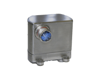
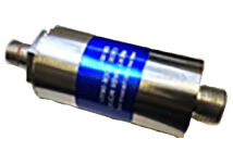
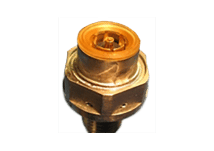
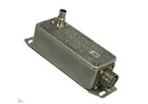
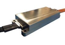
High Voltage Electronic Safe & Arm Device (HV ESAD) and Ignition Safety Devices (ISDs) – (most applicable to an autonomous flight safety system) generate, internal to the device, a high voltage spring down signal that can be used to directly initiate a secondary explosive in the form of an exploding foil initiator.
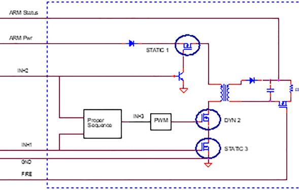
The key takeaway to the HV ESAD design is the multiple arming inhibits. In the diagram below, the bottom left two static and one dynamic, which is only when all of these initial conditions and inhibit signals are properly satisfied. Does the unit generate high voltage and charge its internal capacitor? Once that capacitor is charged above the All-Fire voltage, the system is considered armed. This may be done in different ways depending upon the mission scenario. For instance, in a launch vehicle, the system is armed on the ground with verification provided of the arm status prior to launch. In a more tactical environment, the missile will be armed after first motion. A case such as this may include accelerometers as part of the inhibit logic.
High Voltage Electronic Safe and Arm Details
► Six (6) unique RCC319 compliant and qualified designs
► Single or dual output
► Power on Self Test monitoring all inputs, inhibits, safety switches
► Arm Status Monitor
► Power drop-out protection
► FPGA is an Actel Anti-Fuse
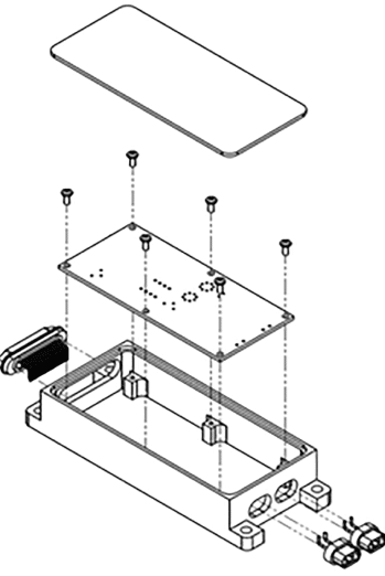
When a terminate command is received by the ESAD, this will convert its high voltage signal to a low energy exploding foil initiator (LEEFI). The detonating output of the LEEFI can be used to drive a variety of termination systems, again depending upon the mission scenario. We can function a cutter or a fuel shutoff valve for thrust termination. Or an explosive ordnance system using a shape charge is shown kind of in the middle or a bulk destruct charge in the upper right for an explosive destruct system.
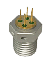
LEFFI
PACSCI EMC FTS System Components – RCC-319 Qualified
► ESAD
► High Voltage Cable
► LEEFI
► ETL
► Destruct Charge(s)
► Motor Venting Charge and/or Skin Separation Charge
► Wire Cutters
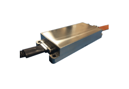
ESAD

SKIN SEVERANCE CHARGE

BULK DESTRUCT CHARGE
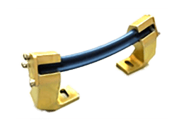
MOTOR VENTING CHARGE
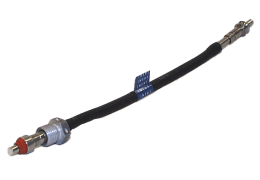
ETL
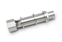
WIRE CUTTER
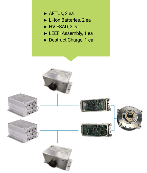
Typical FTS Kit = 2 High Voltage ESAD + 1 LEEFI Assembly + 1 Destruct Charge
► Our ESAD provides safety logic and firing energy for provided LEEFIs
► One Ordnance Destruct Charge per vehicle stage is typically adequate
Test Outcome
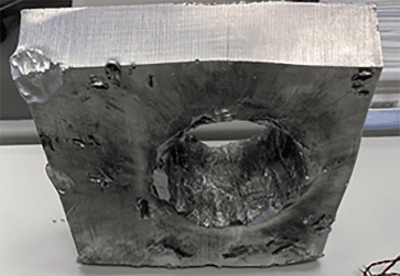
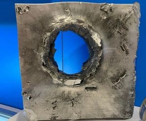
The system includes redundant ESADs initiating the LEEFIs which initiate the desired ordnance that are directly installed into it. In this case, a bulk destruct charge, the LEEFIs will directly initiate the explosive powder in the destruct charge. Here we show a two-and-ahalf-inch thick aluminum plate, along with the hole created by this destruct charge. This is after defeating 150% customer furnished target material. A very capable device, indeed.
PROVIDING SYSTEM POWER
To finish off the system, we need to provide power to both the AFTU and the FTS. SIL batteries have gone through Range Safety qualification programs with extreme shock, vibration, thermal cycle and vacuum testing. The temperature ranges normally -10 to +60°C without a heater and -40 to +60°C with a heater. These are FTS batteries and telemetry avionics for launch vehicles, missiles, and many other platforms.
A COMPLETE AFSS SOLUTION
One of the simplest, yet complete autonomous flight safety system solutions kit is shown below with AFTUs used on the far left and powered by two redundant batteries (top and bottom images) which also power the redundant ESADs. On each stage we would initiate some type of ordnance device, in this case a destruct charge is shown.
