GEOMETRIC SHOCK INITIATION OF ENERGETIC MATERIALS
Experiments have shown that shock energy can be optimized by converging shock waves. The use of refractive and reflective lenses to converge shock waves has been documented experimentally and theoretically. This paper reviews technical literature on experiments and applications of wave mechanics to shock wave propagation, and establishes a unique method for analyses of shock waves.
Robert Weinheimer
Published: 19th International Pyrotechnics Seminar, February 1994
Abstract
This paper describes a method of analyzing shock wave initiation of energetic materials (EM) using the application of wave mechanics with principles derived from geometric optics(1). This approach is attractive in two ways; 1. The principles of shock wave mechanics can be derived from the science of geometric optics and; 2. When these principles are applied to shock wave initiation experimentation, the results have been consistently predictable.
Wave mechanics as used in this paper is confined to the application of the principles of geometric optics to the shock waves of particles of matter. The principles of wave mechanics to shock wave propagation are based upon the following premises:
1. A propagating planar shock wave front will respond to interfaces of different media in the same manner as light rays respond to a lens.
2. A propagating planar shock wave front will refract and/or reflect at the interface of the curved surface of media having different impedance.
3. The angle of refraction and reflection will be determined by the angle of the shock wave front incidence to the normal of the surface, and the impedance difference (index of refraction) of the two media at the interface.
The ordnance designer can use principles already well established in geometric optics to predict shock wave energy vectors propagating through a medium. He can then optimize the design for initiation shock energy within an energetic material (EM).
SUMMARY:
The use of refractive and reflective lenses to converge shock waves have been documented experimentally and theoretically. This paper reviews technical literature on experiments and applications of wave mechanics to shock wave propagation, and establishes a unique method for analyses of shock waves. The derivation of the principles of geometric optics applied to predicting shock wave propagation is discussed. Experiments applying the principles of geometric optics to shock initiate BKNO3, Ti-KClO4, Zr-KClO4, PETN, and HNS II is described. Observations of 304L stainless steel response to shock waves influenced by material grain direction versus shock wave vector are also briefly discussed.
CONCLUSION:
1. Shock initiation threshold of energetic materials (as tested) in ascending order are PETN (most sensitive), Zr-KClO4, Ti-KClO4, TiH0.65-KClO4, BKNO3, HNS II (least sensitive).
2. This wave mechanics approach can be applied to macro and micro design analysis (nuclear, FAE, and conventional devices, specifically a thru-bulkhead-initiator (TBI)), to improve initiation reliability.
3. The geometry of material separation (pockets), piping, and spalling caused by shock waves, as observed in 304L stainless steel appears to be dependent on material grain direction.
Literature Review
Experiments have shown that shock energy can be optimized by converging shock waves. The following literature review shows a progression that supports the shock theory proposed in this paper.
Schrodinger:
Schrodinger (1) in his 1933 Nobel lecture states from Fermat’s definition “In different media, light propagates with different velocities…” In Wave Mechanics the mechanical system is comparable to the wave theory of light with wavelengths of “waves of matter”
Guderly:
Guderly (2) in 1942 (translated from the German) states, “The pressure behind a spherical shock wave, which is propagating toward its center, approaches infinity on nearing the center.” This paper describes the Geometric Physics analyses used for predicting the initiation pressures and temperatures required to initiate a nuclear chain reaction.
Axford & Ham:
Axford and Holm (3) in 1978 apply numerical solutions to self-similar shock convergence. They explain theoretically that the energy density of a spherically imploding shock wave will increase proportionately, from its origin at the surface of a sphere to its center, as an inverse function of the radii, minus the attenuation properties of the shock-host medium and the perturbation caused by imperfect converging forces. Note: While Axford, Holm, and Guderly described applications to direct an explosive shock by imploding convergence in detail, they make no reference to refractive convergence, which is the principle that describes the geometric shock theory presented in this paper.
Winterberg:
Winterberg (4) in 1981 described explosive devices that use geometric cavitation, containing an explosive, to reflect shock waves off a surface, and refract the shock wave through a lens to a focal point. The converging shock wave increases in energy density in the form of temperature and pressure under inertial confinement.
Heidemann:
Heidemann (5) in 1969 was awarded a patent on a “One Way Detonation Device and Assembly” (aka explosive diode). The patent details a device in which “the conical end wall causes shock waves created by the detonation of a donor charge to converge along a line within the acceptor charge to initiate the acceptor charge. Conversely, when the acceptor charge is detonated, the conical end wall causes divergence or outward spreading of the shock waves so that the donor charge is not detonated.”
Munroe-Neumann:
The Munroe-Neumann (6) explosive shaped charge (without liner) effect is an example of the energy amplification available from converging shock waves. Plasma mach stems of three times the explosive detonation velocity (25,000 m/s) have been achieved.
Bowden:
Bowden (7) in 1963 observed shock wave formations influenced by geometric surface termination of an explosive. Munro jets resulted from the converging shock waves of these experiments.
Carlson & Zapf:
Carlson and Zapf (8) in 1976 were awarded a patent on a through-bulkhead explosion initiation device (aka donorless through-bulkhead initiator). Although not mentioned in the text, 4 the sketch depicts a design that would converge a shock wave along the center axis of the acceptor charge.
Thivet, Lecloitre & Guy:
Thivet, Lecloitre, and Guy (9) in 1982 presented a paper describing the scientific method used to design a donorless TBI for the ARIANE launch vehicle. The text states that a spherical (bulk) head would favor the convergence of the shock wave. However optimization using a geometrically curved bulkhead was not pursued in this study.
Lombard et al:
Lombard et al. (10) in a 1982 technical paper reported success with shock initiation of pyrotechnic compositions within a donorless through-bulkhead initiator design. The explosive end-tip initiated TBI is currently being used on the ARIANE. The device is manufactured by the Societe Nationale Des Poudres Et Explosifs (SNPE) for national (France) defense applications.
Hardt & Martinson:
Hardt and Martinson (11) in a 1974 presentation to the 8th Explosive and Pyrotechnic Symposium, described the shock initiation of pyrotechnic compositions by flier plate impact as “…shock compression elevates the temperature (through the adiabatic process) until auto ignition is attained.”
Searcy & Schwartz:
Searcy and Schwarz (12) describe propagation of a shock wave through a metallic medium having a flat-bottom cylindrical cavity perpendicular to the plane of the wave. The shock is transmitted into the metallic medium by flier-plate impact. The impacted area is larger than the diameter of the cylinder cavity containing energetic material within the metallic medium. The shock wave overlaps the flat-bottom cavity and creates a “toroidal” shock wave converging toward the axis of the cylindrical cavity.”
M. Bursco:
M. Busco (13) applies a variation of Fermat’s geometric optic principle to design detonation wave generators where the detonating wave front is shaped by the geometry of the explosive.
Geometric Physics
Geometric Physics is defined within this paper as the study of the effects of geometric influences on shock waves in non-reactive and reactive mediums. Experiments and test data results suggest that the mechanics of shock waves obey the kinematics principles of geometric optics. These experiments show that a free-traveling planar shock wave can be converged and focused, thus concentrating the shock-wave energy density.
In this context, we apply kinematics in the study of shock-wave vectors.
Huygens’ Graphic Analysis of Shock Propagation
The Engineering Design Handbook (15) makes this statement on wave shaping: “All techniques (of shock wave analysis) are essentially applications of Huygens’ principles that form the basis of geometric optics.” The smoked foil witness technique used by Strehlow et al (16) captured patterns of Huygens’ spherical wave forms.
Huygens’ Principles
Huygens’ principles of geometric optics will be used to illustrate graphically the kinematics of shock waves. Huygens’ principles are graphically illustrated with the use of circles and arcs to represent the advancing shock wave propagation.
Huygens’ First Principle
Huygens’ first principle states that every point on an advancing wave front of light (shock) can be a source of secondary waves, which in an isotropic medium move away from the point of origin as spherical wavelets.
Huygens’ Second Principle
Huygens’ second principle states that the new position of the wave front is the envelope of wavelets emitted from all points of the wave front in the previous position.
Shock Wave Propagation in Nonreactive and Reactive Mediums
Shock waves propagating in nonreactive and reactive mediums can be modeled using Huygens’ analysis in four ways as shown in Figure 1:
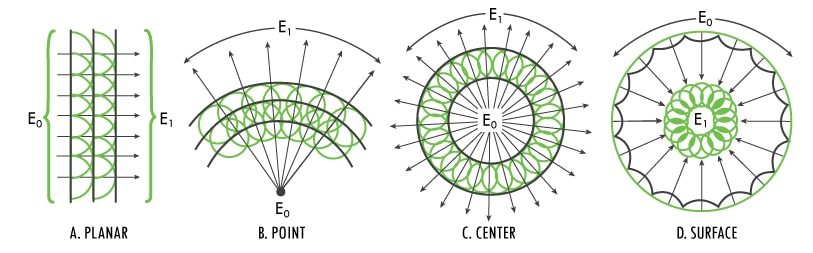
- Figure 1a. is planar shock wave
- Figure 1b. is point initiated
- Figure 1c. is center initiated
- Figure 1d. is surface initiated
To achieve models of general value, we consider isotropic shock-wave forms. In a center initiated spherical shock wave (Figure 1c), shock waves will travel radially outward from their origin within the sphere. The shock-wave front will expand radially in spherical form and the energy is diffused into the surrounding mass at the shock front. The diverging shock wave energy fills a larger volume (R1 value increasing), is dissipated, and the shock wave energy density decreases with the third power of the radii, and can generally be illustrated by:
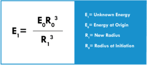
Reversibly, a spherical, converging (R1 value decreasing) shock wave simultaneously initiated over its spherical surface creates a shock wave pressure propagating toward its center, theoretically increasing the energy density toward infinity on nearing the center (Figure 1d).
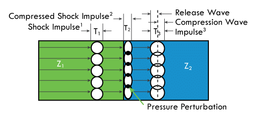
Shock waves are attenuated in nonreactive and reactive media according to the impedance (mechanical properties) of the materials (Figure 2). The impedance of a homogeneous medium is directly related to its mechanical properties. The material’s mechanical properties will determine the amount of shock energy that is absorbed in the deforming compression wave (shock) and recovered in the elastic release wave.
A shock impulse at time one (Tl) propagating through a homogeneous medium of impedance one (Z1) has incidence at the interface of impedance two (Z2) which is twice the impedance of Z1. The shock wave enters Z2 as a compression wave (shock impulse 2) at time two (T2). At the moment the impulse width fully enters Z2, a release wave in the opposite direction of the wave front begins to dilute the shock energy and reduce the shock impulse.
Laws of Refraction
Before we apply the principles of geometric optics to analyze shock-wave phenomena, we redefine the laws of refraction to apply to shock waves as follows:
Refraction of Shock
When a shock wave strikes the boundary between two shock-transparent media, a certain part of it is reflected, but in general a much larger part passes into the second medium with a sudden change in direction, called refraction.
This phenomenon occurs in accordance with three empirical laws:
First Law of Refraction
states that the incident shock wave, the refracted shock wave, and the normal to the plane surface of incidence lie in the same plane (Figure 3).
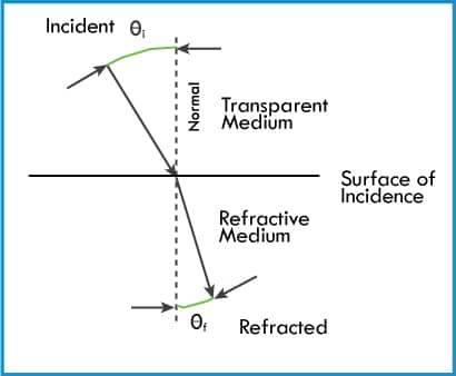
Second Law of Refraction
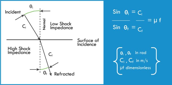
states that the ratio of the sine of the angle of incidence (Øi), measured from the normal to the surface of incidence, to the sine of the angle of refraction (Øf) measured from the same normal is a constant (µf) specific for the two media, and equals the ratio of the velocity of the incidence wave (Ci) to the velocity of refraction wave (Cf) The resultant µf is the index of refraction (Figure 4).
Third Law of Refraction
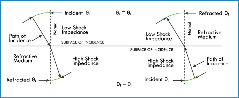
states that the path of incidence and the refraction of the shock wave at the interface of two media is reversible (Figure 5).
Principles of Shock Refraction:
On the bases of the laws of refraction, we state our principles of shock refraction (Figure 6). If the shock velocity is faster in the first medium (Figure 6a.) than in the second, the shock wave will be refracted toward the normal of the curve. If the shock velocity is faster in the second medium (Figure 6b.), the shock wave will be refracted away from the normal.

Geometric Shock Initiation of Energetic Materials
We will use the application of Huygens’ graphic analysis to evaluate geometric shock initiation of energetic materials
Flat-Bottom Cylindrical Cavities
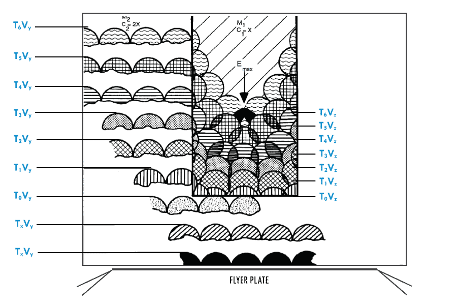
Let us first examine the effect of a shock wave incident on a cylindrical cavity. Figure 7 illustrates a planar shock wave being transmitted through a metal body having a flat-bottom cylindrical cavity in its center. The material of the body (M2) has a shock-velocity constant (C2M = 2x) greater than the material filling the cavity (M1) where the shock velocity (C1=x) is impeded. The velocities can be determined by examining the Hugoniot (Equation of State) of the materials. For the purpose of illustration, a ratio of velocity has been selected at 2 to 1. In Figure 7, Tx = time, Vy = shock velocity in M2, and Vz = shock velocity in M1. The M2 C2, being faster, generates radial shocks into M1 at the cylinder wall surface. At point T5Vy the radial shock meets the planar shock along the center axis of the cylinder cavity. The shock wave will converge along the center axis of the cylinder increasing the energy density in the form of temperature and pressure (Emax) to the EM initiation threshold.
Parabolic-Bottom Cylindrical Cavities
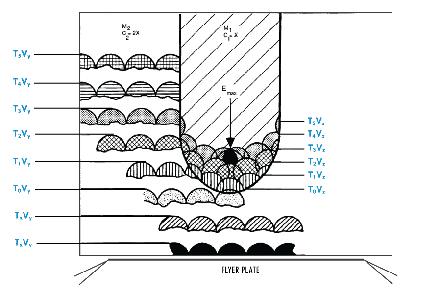
Now we compare the shock wave incident’s effect on a cylindrical cavity with a parabolic surface (curved bottom). In Figure 8, the shock incident at the parabolic interface between M1 and M2 responds to the law of refraction and the shock vector changes toward the normal of the curve. The shock wave converges on the center axis of the cylinder. The faster shock velocity in M2, cause shocks radially into M1 along the cylinder wall. At a point along the cylinder cavity axis, the shock vectors intersect (Emax), the shock wave energy density reaches a peak level as it collapses and forms a Mach Stem at the focal point (caustic) of the parabola.
ANALYSIS
A kinematics Huygens’ graphic analysis of shock wave propagation in a flat-bottom EM cavity, Figure 7, and a parabolic-bottom EM cavity, Figure 8, shows higher energy densities are attained earlier at the focal point in figure 8.
Refraction of the shock wave at the parabolic surface (Figure 8) refracts the shock wave vector toward the normal of the curve. The shorter distance to the center (focal point) of the cavity 11 conserves energy and the shock arrives at the focal point creating an increase in energy density (Emax) at T3Vz.
Note that in the flat-bottom cavity (Figure 7) the converging shock arrival is at T6Vz time interval and in the parabolic-bottom (Figure 8) the converging shock arrival is at T3Vz.
Experimental Approach
An experiment had been devised to establish the general validity of the application of geometric shock wave theory to initiate energetic materials. The technical objectives of the experiment were to:
1. Observe the flash characteristics of initiation of a given energetic material (EM) as a function of barrier thickness
2. Utilize geometric configurations in barrier cavities guided by the principles of geometric optics
3. Record the increase or decrease of barrier thickness as a function of the shock initiation sensitivity limits of the EM
Flat-Bottom Cavity
The design baseline configuration comprises opposing flat-bottom cavities in a 304L stainless steel body (Figure 9). The barrier receives a shock stimulus from an explosive booster end tip initiated by a confined detonating cord, which is initiated by an electrical detonating cap.
The sequence of explosive events (Figure 10) is as follows:
1. An electrical stimulus initiates the electric detonating cap.
2. The detonating cap shock initiates the confined detonating cord.
3. The confined detonating cord propagates to, and detonates, the explosive end-tip booster.
4. The end-tip shock wave and/or flyer plate (there is a gap between end-tip and barrier) includes a shock stimulus to the barrier.
5. The shock is transmitted from the barrier into…
6. The cavity of energetic material and induces a shock stimulus to the energetic material. If the energetic material exceeds its shock sensitivity threshold for initiation, the energetic material reacts violently.

Parabolic-Bottom Cavity
The parabolic design chosen for the experiment was a 0.100 in. diameter EM cavity. Two methods were tried to effect the parabolic shape (Figure 11), 1. parabolic die punch deformation, and 2. quasi-parabolic drilling. To conserve resources, the second (quasi-parabolic) method was selected (see Figure 11).
Parabolic Die-punch Deformation:
A cavity was drilled in a 304L SS test block with a standard 0.100 in. diameter drill bit. A 0.390 in. diameter donor port was drilled from the opposite side with a common centerline with the 0.100 in. EM cavity. The barrier thickness (see Figure 10. (5) barrier) is the distance between the 0.390-in. donor port and the 0.100-in. EM cavity. A 0.097 in. diameter die punch machined with a parabolic tip is inserted into the 0.100- in. cavity. A force is applied against the barrier until parabolic deformation is achieved. This method also caused some translated deformation to the flat bottom of the 0.390-in. port.
Quasi-Parabolic Drilling:
A standard 0.100-in. diameter drill bit was modified at its tip to a 0.030 in. radius point with an included cutting angle of 110 deg. Using a 304L SS test blank with a 0.390-in. donor port on one end, a 0.100-in. EM cavity was drilled from the blank end having a common axial centerline with the port. The EM cavity bottom drilled by the modified drill bit was accepted as a quasi-parabolic geometry.
Instrumentation:
The only recording instrument used was a Polaroid camera and a mirror to catch the reflected go/no-go initiation event in a dark enclosed chamber (Figure 12).
Summary of Results
Further experimentation is needed to detail the values of geometric shock convergence. However, the following general results can be stated.
The flat-bottom EM cavity’s ability to influence the initiation of the energetic material increases with the increase of the shock-stimulus impact area (port). The energetic material TiH0.65/KClO4 did not initiate in a 0.200-in-diameter flat-bottom cavity and a barrier thickness of 0.100-in. Initiation of TiH0.65/KClO4 did occur when the cavity diameter was reduced to 0.100-in. diameter, Figure 13a.. Optimization of shock-stimulus donor port impact area ratio to the EM cavity was not investigated. It would be valuable knowledge to detail the optimization of the donor port-to-EM cavity ratio for a given shock stimulus.
The energetic materials tested were selected on availability and application interest. The descending order of shock initiation threshold sensitivity as tested in a quasi-parabolic-bottom EM cavity, Figure 13b., was PETN (the most sensitive), Zr-KClO4, Ti-KClO4, TiH0.65-KClO4, B-KNO3, and HNS II (the least sensitive).
Notes:
1. The density of energetic material influences the EM shock initiation sensitivity threshold. All EM samples were consolidated between 10ksi and 30ksi. Consolidation loads were recorded. There are not enough data points to give a reliable correlation between EM consolidation and initiation sensitivity threshold barrier thickness.
2. PETN sensitivity should be verified as it was a surprise to the author that it was more sensitive to shock than Zr-KClO4 and therefore should be retested for confidence in the result.
PETN photographic results (Figure 12.) were interpreted to record an occurrence of a transition from detonation to deflagration at a barrier thickness of approximately 0.140 in. The deflagration continued to occur to a barrier thickness of 0.190 in. (the limit of testing conducted). Additional testing would be required to determine the failure to initiate barrier thickness for PETN.
Zr-KClO4 tested successfully in a parabolic-bottom EM cavity with a 0.125 in. barrier thickness, where testing ended for conservation of resources.
Ti-KClO4, test resulted in successful initiation to 0.140 in. barrier thickness.
TiH0.65-KClO4 data indicates a flat-bottom EM cavity initiation threshold level is approximately at a barrier thickness of 0.133 in., while a quasi-parabolic-bottom cavity had successful initiation to 0.181 in. barrier thickness, where testing ended to conserve resources. See note below.
B-KNO3 testing resulted in failure to initiate at the baseline barrier thickness of 0.100 in., while a quasi-parabolic-bottom EM cavity initiated B-KNO3 at 0.125 in. barrier thickness, at which point resources were depleted and testing ended.
HNS results from a single test indicated it to be the least sensitive, however the author cautions that additional testing needs to be performed for verification.
Note:
A redundant donor cavity test hardware, Figure 13c., was tested using a single donor with failure to ignite TiH0.65-KClO4 with a barrier thickness of 0.100 in. A redesigned, Figure 14, redundant donor cavity hardware was successful in initiation of TiH0.65-KClO4 at 0.100 in. barrier thickness. Only these two tests were performed.
Observations
The author thought it to be important that the following test hardware spalling observations be reported:
The 304L stainless steel expended test hardware was cross sectioned to examine the barrier damage by shock wave spalling. The observations of the cross sections lead to the following postulation:
The degree of deformation is determined by the strength of the shock wave and the area of free surface as the shock wave exits the media into a media of porous EM. The deformation occurs in the form of delamination along grain direction boundaries.
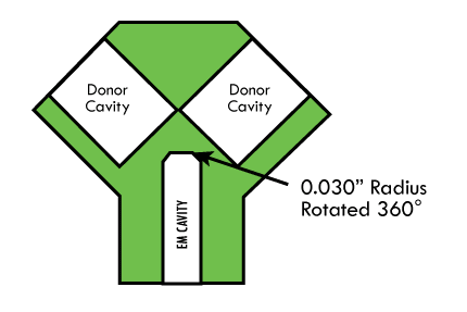
A parabolic bottom cavity was tested using a single donor in the redundant donor cavity hardware, Figure 13c. The result was a failure to initiate TiH0.65-KClO4. A review of the design using Huygens’ graphic analysis indicated a flat bottom cavity with a corner radius, Figure 14, may be more efficient in a redundant donor cavity design.
A flat bottom cavity with a machined 0.030″ corner radius rotated 360° around the bottom was manufactured and tested with successful results. The redesign was limited to a single test.
Although the material failure is in tension, the inherent shear stress in the 304L SS is the cause of failure. The material actually fails in tension along the shear stress planes created during the plate rolling or bar extrusion manufacture process.
Grain directions in 304L SS are created during manufacture process of plate rolling and bar extrusion. The direction of the grain is set by the direction of the plate rolling or bar extrusion.
During the plate rolling or bar extrusion manufacture process ( assuming the force is applied toward the center of material), the 304L SS is stretched in the direction of roll/extrusion. This causes a gradient motion of the material. First motion is at the surface where the force is applied and then gradates inward toward the center. The grading tensile loads creates shear stress planes parallel to the direction of roll/extrusion. A method to help relieve some of the stress is to heat treat under a double vacuum melt process.
Knowing the grain direction (grain boundaries) of the test hardware, it has been observed that the spalling pockets within the bulkhead were consistently elongated in the direction of the material’s grain direction regardless of the direction of the passing shock wave. This phenomenon should be the subject of a future study. See Figure 13 a, b, c, d, and e.
The pocket (spalling) is caused by failure in tension (Figure 13) of the 304L SS material. The separation of the 304L SS grain boundaries can be explained by the shock wave front compressing (increasing the density) and displacing the material particles in the direction the shock wave is traveling. The particles behind the shock front are traveling at varying velocities as a result of the boundary conditions (surroundings), which tend to dissipate the shock compression and return the material to its normal density. This dissipative rarefaction wave follows in behind the shock front, so that the density is decreased. When two such rarefaction waves, traveling in different directions intersect, the material is accelerated (pulled) in two opposing directions, and this produces a state of tension in the material.
It was also observed that the spalling was least in the test sample having the curved parabolic and quasi-parabolic EM cavities. These observations could lead to designs that would mitigate the spalling ejecta of the medium surface as a shock wave leaves the surface of the one medium into a medium of a much lower impedance (air).
References
- Erwin Schrodinger, The Fundamental Idea of Wave Mechanics, Nobel Prize Physics Award Address, 1933, Elsevier Publishing Co., & Nobel Foundation
- G. Guderly, Strong Spherical and Cylindrical Shock Waves in the Neighborhood of the Center of the Sphere or the Axis of the Cylinder. Report of the Institute for Gas dynamics of the Herman Goring Aviation Research Institute, Braunschweig, Luftfahrtforschung, Vol. 19, No. 9, translated by C.E. Witliff, Oct. 1942, pp 302-312.
- R.A. Axford and D.D. Holm, Spherical Shock Collapse in a Non-Ideal Medium. IVTAM/IMU Symposium, Novosibirsk, USSR, 1978.
- Friedwardt Winterberg, The Physical Principles of Thermo-Nuclear Explosive Devices. University of Nevada, Fusion Energy Foundation, New York, 1981.
- W.B. Heidemann, One-Way Detonation Transfer Device and Assembly. Explosive Technology, Inc., Fairfield, California, US Patent 3,460,477, Aug. 12, 1969
- Detonation, Munroe-Neumann Effect (or Shaped Charge Effect) and Lined Cavity Effect. Encyclopedia of Explosives and Related Items, Picatinny Arsenal, P. D442
- F.B. Bowden, The Initiation and Growth of Explosion in the Condensed Phase, University of Cambridge (post 1963)
- B. V. Carlson and D. C. Zapf, Through-Bulkhead Initiation. US Patent 3,945,322, Mar. 23, 1976, assignee: USA Secretary of the Navy
- R. Thivet, J. Lecloitre, and L.R. Guy, Theoretical and Experimental Study of a Through Bulkhead Detonator, 8th International Pyrotechnic Seminar, Steamboat Springs, Colorado, Jul. 1982.
- J.M. Lombard et al., Shock Ignition Thorough Metallic Bulkhead of Various Pyrotechnic Compositions, 8th International Pyrotechnic Seminar, Steamboat Springs, Colorado, Jul. 1982
- Alexander P. Hardt and Riho H. Martinson, Initiation of Pyrotechnic Mixtures by Shock. 8th Explosive and Pyrotechnic Symposium, Feb. 1974
- J.Q. Searcy and A.C. Schwarz, Geometrical Shock Focusing and Flying Plate Initiation of Solid Explosives. 6th Symposium (International) on Detonation, Aug. 1976
- M. Busco, Optical Properties of Detonation Waves, 5th Symposium (International) on Detonation, Aug. 1970
- H.S. Yadav et al., Design of Plane Wave Lens by Metal-Explosive Combination, Explosive Stoffe, Oct. 1969
- Engineering Design Handbook – Explosives Series – Explosive Trains . AMCP 706- 179, Jan 1974
- Roger A. Strehlow et al., Transient Studies of Detonation Waves, Astronautica Acta, Vol. 17, Great Britain Pergamon Press, 1972, pp. 509-527
- R. Weinheimer, Geometric Shock Initiation of Pyrotechnics and Explosives, oral presentation at ADPA, John C. Stennis Space Center, Mississippi, 4 – 5 October 1989, Mcdonnell Douglas Aerospace