
Mechanical Pull Initiators
Product Description
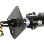
Mechanical Pull Initiators are used to initiate a Canopy Fracture Systems (CFS) and Transparency Removal Systems (TRS). They rely on the upward movement of the ejection seat or pulling of an attached cable to pull a shaft(s) or have the seat strike a ‘trip’ lever on a firing pin mechanism to function (fire) the initiator. The initiators can be configured for single or dual firing pin mechanisms and single or dual output. Examples of the initiators we’ve designed are shown at right.
Key Features
- Used to initiate an escape system (ground or air)
- Explosive loaded & inert
- Provides output stimulus to activate system & direct sequence mode
- Cockpit, seat rail & external panel mounting common
- Arm/fire: two actions to activate
- Turn / Push or Pull
- Button/Bar Press / Push or Pull
- Shear Pin Sever / Pull
- Pull, rotational & push forces meet Mil-Std-1472 human factors engineering requirements
How Mechanical Pull Initiators Work
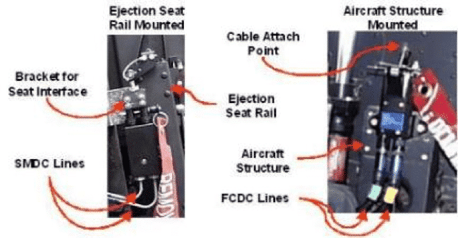
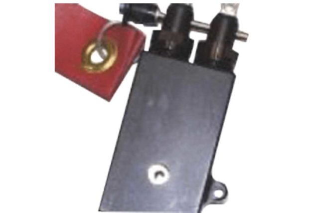
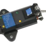
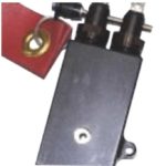
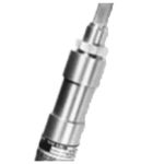
Dual firing pin mechanisms like the T-38 unit utilize a cross bracket assembly attached to the top of the initiator. This provides the interface with the ejection seat and ensures the firing mechanisms pull equally. The cross bracket can be adjusted to take into account any difference between the mount point of the pull initiator on the rail and the attachment point on the ejection seat. Attachment to the seat occurs without preload. This ensures the safety pin can be removed and installed easily without risk to the individual performing the task.
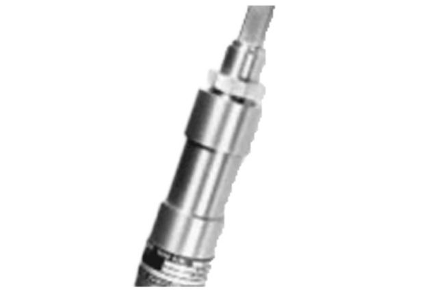
One of the factors in designing a Mechanical Pull Initiator’s configuration is dependent upon their installation location. For initiators attached to the seat rail, the firing pin pull shafts are attached to the top of the ejection seat by means of a bracket assembly / seat attachment bolt interface. For cockpit attachments the initiator has a protruding lever that is struck by the seat. The basic function of each is the same, single or dual, seat pull or trip. As with the Internal Arm Fire Initiator (IAFI)and External Arm Fire Initiator (EAFI), the upward movement of the seat activates a similar firing pin mechanism, compressing a spring, reaching a release point and expanding the spring to for the firing pin to strike the PP. Below are examples of seat rail and cockpit mounted installations
Applications
Primarily aircraft & space applications our mechanical pull initiators can be found on:
- AH-1
- C-17
- CASA-101
- T-38A/N P
- C-9
- CASA-101
- S-3 Viking
- NASA T-38A/N
- C-17
- T-6
- Mirage F-1
- Alpha Jet
- Scorpion
- Honda Jet
- AW609
Specifications
- Operating Temperature
–65°F to +200°F - Leak Rate
1×10⁻⁵ cc/sec. Air at 1.1 + 1Atmosphere - Low Temperature
Conditioned at -80°F for two hours, –65°F for 70 hours then fired successfully. - High Temperature
Conditioned at +200°F for 50 hours, functioned successfully - Iced Condition
MIL-C-83124 paragraph 4.5.11.10: Temperature –80°F & stabilized, then placed in 100°F/90% relative humidity until ice disappears, then –80°F & stabilized then fired at –80°F - Altitude
Placed in vacuum chamber at 1.32 inches Hg and temperature of –65°F. Conditioned for one hour and functioned with no performance degradation. - Submerged Condition
MIL-C-82124: Submerged in water tank then tank pressurized to 17.75 psig to simulate 40 feet, then fired. - Shock
MIL-STD-810, Method 516, Procedure 1: Peak Amplitude of 30 G for 11 milliseconds; Shock pulse wave form: Terminal peak saw tooth for a total of 18 impacts. - Temperature Shock
100 cycles between –70°F and +200°F with 55 minute duration at each extreme then units functioned with no adverse effect. - Temperature, Shock, Humidity & Altitude (TSH&A): MIL-C-83124, Paragraph 4.5.11.7 at 70K Feet Altitude
- Lock Shut
MIL-C-83124, Paragraph 4.5.12.1, Devices lock shut then fired at –65°F and +200°F - Vibration
MIL-STD-810, Method 514, Procedure I, parts 1-3, Procedure I, & curve z at –65°F, +70°f, and 200°F - Salt/Fog
MIL-STD-810, Method 509: 5%+1% Sodium Chloride by Weight for 48 Hours plus 48 Hours drying time. Fired at 70°F. - Dust
MIL-STD-810 Method 510, Except High Temperature 200°F. - 6 Foot Drop
Dropped Firing Mechanism Up, Firing Mechanism Down and Side, then fired - 40-Foot Drop
IAW MIL-STD-331A, Test 103.1 Procedure 1 Dropped Firing Mechanism Up, Firing Mechanism Down and Side. Units did not fire and were safe to dispose of. - Humidity
Per MIL-STD-810 Method 507 Procedure I except relative humidity was 100% and temperature +200°F with no adverse effect.
Interface